Basic principles
The transformer is based on two principles: firstly, that an electric current can produce a magnetic field (electromagnetism) and secondly that a changing magnetic field within a coil of wire induces a voltage across the ends of the coil (electromagnetic induction). By changing the current in the primary coil, it changes the strength of its magnetic field; since the changing magnetic field extends into the secondary coil, a voltage is induced across the secondary.
A simplified transformer design is shown to the left. A current passing through the primary coil creates a magnetic field. The primary and secondary coils are wrapped around a core of very high magnetic permeability, such as iron; this ensures that most of the magnetic field lines produced by the primary current are within the iron and pass through the secondary coil as well as the primary coil.
Induction law
The voltage induced across the secondary coil may be calculated from Faraday's law of induction, which states that:
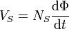
where VS is the instantaneous voltage, NS is the number of turns in the secondary coil and Φ equals the magnetic flux through one turn of the coil. If the turns of the coil are oriented perpendicular to the magnetic field lines, the flux is the product of the magnetic field strength B and the area A through which it cuts. The area is constant, being equal to the cross-sectional area of the transformer core, whereas the magnetic field varies with time according to the excitation of the primary. Since the same magnetic flux passes through both the primary and secondary coils in an ideal transformer,[1] the instantaneous voltage across the primary winding equals

Taking the ratio of the two equations for VS and VP gives the basic equation[7] for stepping up or stepping down the voltage

Ideal power equation
If the secondary coil is attached to a load that allows current to flow, electrical power is transmitted from the primary circuit to the secondary circuit. Ideally, the transformer is perfectly efficient; all the incoming energy is transformed from the primary circuit to the magnetic field and into the secondary circuit. If this condition is met, the incoming electric power must equal the outgoing power.
- Pincoming = IPVP = Poutgoing = ISVS
giving the ideal transformer equation
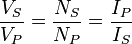
If the voltage is increased (stepped up) (VS > VP), then the current is decreased (stepped down) (IS < IP) by the same factor. Transformers are efficient so this formula is a reasonable approximation.
The impedance in one circuit is transformed by the square of the turns ratio.[1] For example, if an impedance ZS is attached across the terminals of the secondary coil, it appears to the primary circuit to have an impedance of  . This relationship is reciprocal, so that the impedance ZP of the primary circuit appears to the secondary to be
  .
.
No comments:
Post a Comment