December 7, 2008

some more types of electric motors

AC motors

In 1882, Nikola Tesla invented the rotating magnetic field, and pioneered the use of a rotary field of force to operate machines. He exploited the principle to design a unique two-phase induction motor in 1883. In 1885, Galileo Ferraris independently researched the concept. In 1888, Ferraris published his research in a paper to the Royal Academy of Sciences in Turin.

Introduction of Tesla's motor from 1888 onwards initiated what is sometimes referred to as the Second Industrial Revolution, making possible the efficient generation and long distance distribution of electrical energy using the alternating current transmission system, also of Tesla's invention (1888). Before the invention of the rotating magnetic field, motors operated by continually passing a conductor through a stationary magnetic field (as in homopolar motors).

Tesla had suggested that the commutators from a machine could be removed and the device could operate on a rotary field of force. Professor Poeschel, his teacher, stated that would be akin to building a perpetual motion machine. Tesla would later attain U.S. Patent 0,416,194 , Electric Motor (December 1889), which resembles the motor seen in many of Tesla's photos. This classic alternating current electro-magnetic motor was an induction motor.

Michail Osipovich Dolivo-Dobrovolsky later invented a three-phase "cage-rotor" in 1890. This type of motor is now used for the vast majority of commercial applications.

Components

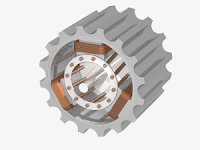
A typical AC motor consists of two parts:

  1. An outside stationary stator having coils supplied with AC current to produce a rotating magnetic field, and;
  2. An inside rotor attached to the output shaft that is given a torque by the rotating field.

Torque motors

A torque motor (also known as a limited torque motor) is a specialized form of induction motor which is capable of operating indefinitely while stalled, that is, with the rotor blocked from turning, without incurring damage. In this mode of operation, the motor will apply a steady torque to the load (hence the name).

A common application of a torque motor would be the supply- and take-up reel motors in a tape drive. In this application, driven from a low voltage, the characteristics of these motors allow a relatively-constant light tension to be applied to the tape whether or not the capstan is feeding tape past the tape heads. Driven from a higher voltage, (and so delivering a higher torque), the torque motors can also achieve fast-forward and rewind operation without requiring any additional mechanics such as gears or clutches. In the computer world, torque motors are used with force feedback steering wheels.

Another common application is the control of the throttle of an internal combustion engine in conjunction with an electronic governor. In this usage, the motor works against a return spring to move the throttle in accordance with the output of the governor. The latter monitors engine speed by counting electrical pulses from the ignition system or from a magnetic pickup and, depending on the speed, makes small adjustments to the amount of current applied to the motor. If the engine starts to slow down relative to the desired speed, the current will be increased, the motor will develop more torque, pulling against the return spring and opening the throttle. Should the engine run too fast, the governor will reduce the current being applied to the motor, causing the return spring to pull back and close the throttle.

Slip ring

The slip ring or wound rotor motor is an induction machine where the rotor comprises a set of coils that are terminated in slip rings to which external impedances can be connected. The stator is the same as is used with a standard squirrel cage motor.

By changing the impedance connected to the rotor circuit, the speed/current and speed/torque curves can be altered.

The slip ring motor is used primarily to start a high inertia load or a load that requires a very high starting torque across the full speed range. By correctly selecting the resistors used in the secondary resistance or slip ring starter, the motor is able to produce maximum torque at a relatively low current from zero speed to full speed. A secondary use of the slip ring motor is to provide a means of speed control. Because the torque curve of the motor is effectively modified by the resistance connected to the rotor circuit, the speed of the motor can be altered. Increasing the value of resistance on the rotor circuit will move the speed of maximum torque down. If the resistance connected to the rotor is increased beyond the point where the maximum torque occurs at zero speed, the torque will be further reduced.

When used with a load that has a torque curve that increases with speed, the motor will operate at the speed where the torque developed by the motor is equal to the load torque. Reducing the load will cause the motor to speed up, and increasing the load will cause the motor to slow down until the load and motor torque are equal. Operated in this manner, the slip losses are dissipated in the secondary resistors and can be very significant. The speed regulation is also very poor.

Stepper motors

Closely related in design to three-phase AC synchronous motors are stepper motors, where an internal rotor containing permanent magnets or a large iron core with salient poles is controlled by a set of external magnets that are switched electronically. A stepper motor may also be thought of as a cross between a DC electric motor and a solenoid. As each coil is energized in turn, the rotor aligns itself with the magnetic field produced by the energized field winding. Unlike a synchronous motor, in its application, the motor may not rotate continuously; instead, it "steps" from one position to the next as field windings are energized and de-energized in sequence. Depending on the sequence, the rotor may turn forwards or backwards.

Simple stepper motor drivers entirely energize or entirely de-energize the field windings, leading the rotor to "cog" to a limited number of positions; more sophisticated drivers can proportionally control the power to the field windings, allowing the rotors to position between the cog points and thereby rotate extremely smoothly. Computer controlled stepper motors are one of the most versatile forms of positioning systems, particularly when part of a digital servo-controlled system.

Stepper motors can be rotated to a specific angle with ease, and hence stepper motors are used in pre-gigabyte era computer disk drives, where the precision they offered was adequate for the correct positioning of the read/write head of a hard disk drive. As drive density increased, the precision limitations of stepper motors made them obsolete for hard drives, thus newer hard disk drives use read/write head control systems based on voice coils.

Stepper motors were upscaled to be used in electric vehicles under the term SRM (switched reluctance machine).

Linear motors

A linear motor is essentially an electric motor that has been "unrolled" so that, instead of producing a torque (rotation), it produces a linear force along its length by setting up a traveling electromagnetic field.

Linear motors are most commonly induction motors or stepper motors. You can find a linear motor in a maglev (Transrapid) train, where the train "flies" over the ground, and in many roller-coasters where the rapid motion of the motorless railcar is controlled by the rail.

Doubly-fed electric motor

Doubly-fed electric motors have two independent multiphase windings that actively participate in the energy conversion process with at least one of the winding sets electronically controlled for variable speed operation. Two is the most active multiphase winding sets possible without duplicating singly-fed or doubly-fed categories in the same package. As a result, doubly-fed electric motors are machines with an effective constant torque speed range that is twice synchronous speed for a given frequency of excitation. This is twice the constant torque speed range as singly-fed electric machines, which have only one active winding set.

A doubly-fed motor allows for a smaller electronic converter but the cost of the rotor winding and slip rings may offset the saving in the power electronics components. Difficulties with controlling speed near synchronous speed limit applications.

Singly-fed electric motor

Singly-fed electric machines incorporate a single multiphase winding set that is connected to a power supply. Singly-fed electric machines may be either induction or synchronous. The active winding set can be electronically controlled. Induction machines develop starting torque at zero speed and can operate as standalone machines. Synchronous machines must have auxiliary means for startup, such as a starting induction squirrel-cage winding or an electronic controller. Singly-fed electric machines have an effective constant torque speed range up to synchronous speed for a given excitation frequency.

The induction (asynchronous) motors (i.e., squirrel cage rotor or wound rotor), synchronous motors (i.e., field-excited, permanent magnet or brushless DC motors, reluctance motors, etc.), which are discussed on the this page, are examples of singly-fed motors. By far, singly-fed motors are the predominantly installed type of motors.

Nanotube nanomotor

Researchers at University of California, Berkeley, recently developed rotational bearings based upon multiwall carbon nanotubes. By attaching a gold plate (with dimensions of the order of 100nm) to the outer shell of a suspended multiwall carbon nanotube (like nested carbon cylinders), they are able to electrostatically rotate the outer shell relative to the inner core. These bearings are very robust; devices have been oscillated thousands of times with no indication of wear. These nanoelectromechanical systems (NEMS) are the next step in miniaturization that may find their way into commercial aspects in the future.

See also:

more types of dc motors

DC Motors

A DC motor is designed to run on DC electric power. Two examples of pure DC designs are Michael Faraday's homopolar motor (which is uncommon), and the ball bearing motor, which is (so far) a novelty. By far the most common DC motor types are the brushed and brushless types, which use internal and external commutation respectively to create an oscillating AC current from the DC source -- so they are not purely DC machines in a strict sense.

Brushed DC motors

The classic DC motor design generates an oscillating current in a wound rotor with a split ring commutator, and either a wound or permanent magnet stator. A rotor consists of a coil wound around a rotor which is then powered by any type of battery.

Many of the limitations of the classic commutator DC motor are due to the need for brushes to press against the commutator. This creates friction. At higher speeds, brushes have increasing difficulty in maintaining contact. Brushes may bounce off the irregularities in the commutator surface, creating sparks. This limits the maximum speed of the machine. The current density per unit area of the brushes limits the output of the motor. The imperfect electric contact also causes electrical noise. Brushes eventually wear out and require replacement, and the commutator itself is subject to wear and maintenance. The commutator assembly on a large machine is a costly element, requiring precision assembly of many parts. There are three types of DC motor:

  1. DC series motor
  2. DC shunt motor
  3. DC compound motor - there are also two types:
    1. cumulative compound
    2. differentially compounded

Brushless DC motors

Some of the problems of the brushed DC motor are eliminated in the brushless design. In this motor, the mechanical "rotating switch" or commutator/brushgear assembly is replaced by an external electronic switch synchronised to the rotor's position. Brushless motors are typically 85-90% efficient, whereas DC motors with brushgear are typically 75-80% efficient.

Midway between ordinary DC motors and stepper motors lies the realm of the brushless DC motor. Built in a fashion very similar to stepper motors, these often use a permanent magnet external rotor, three phases of driving coils, one or more Hall effect sensors to sense the position of the rotor, and the associated drive electronics. The coils are activated, one phase after the other, by the drive electronics as cued by the signals from the Hall effect sensors. In effect, they act as three-phase synchronous motors containing their own variable-frequency drive electronics. A specialized class of brushless DC motor controllers utilize EMF feedback through the main phase connections instead of Hall effect sensors to determine position and velocity. These motors are used extensively in electric radio-controlled vehicles. When configured with the magnets on the outside, these are referred to by modelists as outrunner motors.

Brushless DC motors are commonly used where precise speed control is necessary, as in computer disk drives or in video cassette recorders, the spindles within CD, CD-ROM (etc.) drives, and mechanisms within office products such as fans, laser printers and photocopiers. They have several advantages over conventional motors:

  • Compared to AC fans using shaded-pole motors, they are very efficient, running much cooler than the equivalent AC motors. This cool operation leads to much-improved life of the fan's bearings.
  • Without a commutator to wear out, the life of a DC brushless motor can be significantly longer compared to a DC motor using brushes and a commutator. Commutation also tends to cause a great deal of electrical and RF noise; without a commutator or brushes, a brushless motor may be used in electrically sensitive devices like audio equipment or computers.
  • The same Hall effect sensors that provide the commutation can also provide a convenient tachometer signal for closed-loop control (servo-controlled) applications. In fans, the tachometer signal can be used to derive a "fan OK" signal.
  • The motor can be easily synchronized to an internal or external clock, leading to precise speed control.
  • Brushless motors have no chance of sparking, unlike brushed motors, making them better suited to environments with volatile chemicals and fuels. Also, sparking generates ozone which can accumulate in poorly ventilated buildings risking harm to occupants' health.
  • Brushless motors are usually used in small equipment such as computers and are generally used to get rid of unwanted heat.
  • They are also very quiet motors which is an advantage if being used in equipment that is affected by vibrations.

Modern DC brushless motors range in power from a fraction of a watt to many kilowatts. Larger brushless motors up to about 100 kW rating are used in electric vehicles. They also find significant use in high-performance electric model aircraft.

Coreless or Ironless DC motors

Nothing in the design of any of the motors described above requires that the iron (steel) portions of the rotor actually rotate; torque is exerted only on the windings of the electromagnets. Taking advantage of this fact is the coreless or ironless DC motor, a specialized form of a brush or brushless DC motor. Optimized for rapid acceleration, these motors have a rotor that is constructed without any iron core. The rotor can take the form of a winding-filled cylinder inside the stator magnets, a basket surrounding the stator magnets, or a flat pancake (possibly formed on a printed wiring board) running between upper and lower stator magnets. The windings are typically stabilized by being impregnated with Electrical epoxy potting systems. Filled epoxies that have moderate mixed viscosity and a long gel time. These systems are highlighted by low shrinkage and low exotherm. Typically UL 1446 recognized as a potting compound for use up to 180C (Class H) UL File No. E 210549.

Because the rotor is much lighter in weight (mass) than a conventional rotor formed from copper windings on steel laminations, the rotor can accelerate much more rapidly, often achieving a mechanical time constant under 1 ms. This is especially true if the windings use aluminum rather than the heavier copper. But because there is no metal mass in the rotor to act as a heat sink, even small coreless motors must often be cooled by forced air.

These motors were commonly used to drive the capstan(s) of magnetic tape drives and are still widely used in high-performance servo-controlled systems, like radio-controlled vehicles/aircraft, humanoid robotic systems, industrial automation, medical devices, etc

About servo motor

A servomechanism, or servo is an automatic device which uses error-sensing feedback to correct the performance of a mechanism. The term correctly applies only to systems where the feedback or error-correction signals help control mechanical position or other parameters. For example an automotive power window control is not a servomechanism, as there is no automatic feedback which controls position—the operator does this by observation. By contrast the car's cruise control uses closed loop feedback, which classifies it as a servomechanism.

Servomechanisms may or may not use a servomotor. For example a household furnace controlled by thermostat is a servomechanism, yet there is no closed-loop control of a servomotor.

A common type of servo provides position control. Servos are commonly electrical or partially electronic in nature, using an electric motor as the primary means of creating mechanical force. Other types of servos use hydraulics, pneumatics, or magnetic principles. Usually, servos operate on the principle of negative feedback, where the control input is compared to the actual position of the mechanical system as measured by some sort of transducer at the output. Any difference between the actual and wanted values (an "error signal") is amplified and used to drive the system in the direction necessary to reduce or eliminate the error. An entire science known as control theory has been developed on this type of system.

Servomechanisms were first used in military fire-control and marine navigation equipment. Today servomechanisms are used in automatic machine tools, satellite-tracking antennas, automatic navigation systems on boats and planes, and antiaircraft-gun control systems. Other examples are fly-by-wire systems in aircraft which use servos to actuate the aircraft's control surfaces, and radio-controlled models which use RC servos for the same purpose. Many autofocus cameras also use a servomechanism to accurately move the lens, and thus adjust the focus. A modern hard disk drive has a magnetic servo system with sub-micrometre positioning accuracy.

Typical servos give a rotary (angular) output. Linear types are common as well, using a screw thread or a linear motor to give linear motion.

Another device commonly referred to as a servo is used in automobiles to amplify the steering or braking force applied by the driver. However, these devices are not true servos, but rather mechanical amplifiers. (See also Power steering or Vacuum servo.)

In industrial machines, servos are used to perform complex motion.

History

James Watt's steam engine governor, an automatic speed control, is generally considered the first powered feedback system. The windmill fantail is an earlier example of automatic control, but since it does not have an amplifier or gain, it is not usually considered a servomechanism.

The first feedback position control device was the ship steering engine, used to position the rudder of large ships based on the position of ship's wheel. This technology was first used on the SS Great Eastern in 1866. Steam steering engines had the characteristics of a modern servomechanism: an input, an output, an error signal, and a means for amplifying the error signal used for negative feedback to drive the error towards zero.

Electrical servomechanisms require a power amplifier. World War II saw the development of electrical fire control servomechanisms, using an amplidyne as the power amplifier. Vacuum tube amplifiers were used in the UNISERVO tape drive for the UNIVAC I computer.

Modern servomechanisms use solid state power amplifiers, usually built from MOSFET or thyristor devices. Small servos may use power transistors.

The origin of the word is believed to come from the french “Le-Servomoteur” or slavemotor, first used by Farcot in 1868 to describe hydraulic and steam engines for use in ship steering.

December 5, 2008

Types of dc motors


Types of DC Motors:General data: DC Motors are used in variable speed applications.
Homopolar DC Motor: A direct-current (dc) generator whose poles have the same polarity, with respect to the armature. Thus, no commutator is necessary.
Commutator DC Motor: In a direct-current (dc) motor, generator, or rotating selector, an arrangement of parallel metal bars or strips on a rotating drum. As the drum turns, the bars contact one or more brushes that are in sliding contact with the commutator.
PM DC Motor: [Permanent Magnet] motor uses a permanent magnet instead of armature windings are mounted on the rotor.Permanent Magnet [PM] motors are normally small and produce little horsepower.
Series DC Motor: connect the field windings in series with the armature, used for high-torque loads.
Shunt DC Motor: use high-resistance field winding connected in parallel with the armature.
Compound DC Motor: combine the series and shunt types.

Introduction to alternators

An alternator is an electromechanical device that converts mechanical energy to alternating current electrical energy. Most alternators use a rotating magnetic field but linear alternators are occasionally used. In principle, any AC electrical generator can be called an alternator, but usually the word refers to small rotating machines driven by automotive and other internal combustion engines. In UK, large alternators in power stations which are driven by steam turbines are called turbo-alternators.
History
Alternating current generating systems were known in simple forms from the discovery of the
magnetic induction of electric current. The early machines were developed by pioneers such as Michael Faraday and Hippolyte Pixii. Faraday developed the "rotating rectangle", whose operation was heteropolar - each active conductor passed successively through regions where the magnetic field was in opposite directions. The first public demonstration of a more robust "alternator system" took place in 1886.Large two-phase alternating current generators were built by a British electrician, J.E.H. Gordon, in 1882. Lord Kelvin and Sebastian Ferranti also developed early alternators, producing frequencies between 100 and 300 hertz. In 1891, Nikola Tesla patented a practical "high-frequency" alternator (which operated around 15,000 hertzAfter 1891, polyphase alternators were introduced to supply currents of multiple differing phases.Later alternators were designed for varying alternating-current frequencies between sixteen and about one hundred hertz, for use with arc lighting, incandescent lighting and electric motors
Theory of operation
Alternators generate electricity by the same principle as DC generators, namely, when the magnetic field around a conductor changes, a current is induced in the conductor. Typically, a rotating magnet called the
rotor turns within a stationary set of conductors wound in coils on an iron core, called the stator. The field cuts across the conductors, generating an electrical current, as the mechanical input causes the rotor to turn.
The
rotating magnetic field induces an AC voltage in the stator windings. Often there are three sets of stator windings, physically offset so that the rotating magnetic field produces three phase currents, displaced by one-third of a period with respect to each other.
The rotor magnetic field may be produced by induction (in a "brushless" alternator), by permanent magnets (in very small machines), or by a rotor winding energized with direct current through
slip rings and brushes. The rotor magnetic field may even be provided by stationary field winding, with moving poles in the rotor. Automotive alternators invariably use a rotor winding, which allows control of the alternator generated voltage by varying the current in the rotor field winding. Permanent magnet machines avoid the loss due to magnetizing current in the rotor, but are restricted in size, owing to the cost of the magnet material. Since the permanent magnet field is constant, the terminal voltage varies directly with the speed of the generator. Brushless AC generators are usually larger machines than those used in automotive applications.

Introduction to induction motor

An induction motor (IM) is a type of asynchronous AC motor where power is supplied to the rotating device by means of electromagnetic induction. Other commonly used name is squirrel cage motor due to the fact that the rotor bars with short circuit rings resemble a squirrel cage (hamster wheel).
An
electric motor converts electrical power to mechanical power in its rotor (rotating part). There are several ways to supply power to the rotor. In a DC motor this power is supplied to the armature directly from a DC source, while in an induction motor this power is induced in the rotating device. An induction motor is sometimes called a rotating transformer because the stator (stationary part) is essentially the primary side of the transformer and the rotor (rotating part) is the secondary side. Induction motors are widely used, especially polyphase induction motors, which are frequently used in industrial drives.
Induction motors are now the preferred choice for industrial motors due to their rugged construction, absence of brushes (which are required in most DC motors) and — thanks to modern power electronics — the ability to control the speed of the motor.
History

The induction motor with a wrapped rotor was invented by
Nikola Tesla in 1882 in France but the initial patent was issued in 1888 after Tesla had moved to the United States. In his scientific work, Tesla laid the foundations for understanding the way the motor operates. The induction motor with a cage was invented by Mikhail Dolivo-Dobrovolsky about a year later in Europe. Technological development in the field has improved to where a 100 hp (73.6 kW) motor from 1976 takes the same volume as a 7.5 hp (5.5 kW) motor did in 1897. Currently, the most common induction motor is the cage rotor motor.

December 4, 2008

Basic principles of a transformer

Basic principles

The transformer is based on two principles: firstly, that an electric current can produce a magnetic field (electromagnetism) and secondly that a changing magnetic field within a coil of wire induces a voltage across the ends of the coil (electromagnetic induction). By changing the current in the primary coil, it changes the strength of its magnetic field; since the changing magnetic field extends into the secondary coil, a voltage is induced across the secondary.

An ideal step-down transformer showing magnetic flux in the core

A simplified transformer design is shown to the left. A current passing through the primary coil creates a magnetic field. The primary and secondary coils are wrapped around a core of very high magnetic permeability, such as iron; this ensures that most of the magnetic field lines produced by the primary current are within the iron and pass through the secondary coil as well as the primary coil.

Induction law

The voltage induced across the secondary coil may be calculated from Faraday's law of induction, which states that:

V_{S} = N_{S} \frac{\mathrm{d}\Phi}{\mathrm{d}t}

where VS is the instantaneous voltage, NS is the number of turns in the secondary coil and Φ equals the magnetic flux through one turn of the coil. If the turns of the coil are oriented perpendicular to the magnetic field lines, the flux is the product of the magnetic field strength B and the area A through which it cuts. The area is constant, being equal to the cross-sectional area of the transformer core, whereas the magnetic field varies with time according to the excitation of the primary. Since the same magnetic flux passes through both the primary and secondary coils in an ideal transformer,[1] the instantaneous voltage across the primary winding equals

V_{P} = N_{P} \frac{\mathrm{d}\Phi}{\mathrm{d}t}

Taking the ratio of the two equations for VS and VP gives the basic equation[7] for stepping up or stepping down the voltage

\frac{V_{S}}{V_{P}} = \frac{N_{S}}{N_{P}}

Ideal power equation

The ideal transformer as a circuit element

If the secondary coil is attached to a load that allows current to flow, electrical power is transmitted from the primary circuit to the secondary circuit. Ideally, the transformer is perfectly efficient; all the incoming energy is transformed from the primary circuit to the magnetic field and into the secondary circuit. If this condition is met, the incoming electric power must equal the outgoing power.

Pincoming = IPVP = Poutgoing = ISVS

giving the ideal transformer equation

\frac{V_{S}}{V_{P}} = \frac{N_{S}}{N_{P}} = \frac{I_{P}}{I_{S}}

If the voltage is increased (stepped up) (VS > VP), then the current is decreased (stepped down) (IS < IP) by the same factor. Transformers are efficient so this formula is a reasonable approximation.

The impedance in one circuit is transformed by the square of the turns ratio.[1] For example, if an impedance ZS is attached across the terminals of the secondary coil, it appears to the primary circuit to have an impedance of Z_S\!\left(\!\tfrac{N_P}{N_S}\!\right)^2\!\!
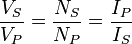
. This relationship is reciprocal, so that the impedance ZP of the primary circuit appears to the secondary to be Z_P\!\left(\!\tfrac{N_S}{N_P}\!\right)^2\!\!.

Fundamental model of generator

Jedlik's Dynamo

Ányos Jedlik's single pole electric starter (dynamo) (1861
In electricity generation, an electrical generator is a device that converts mechanical energy to electrical energy, generally using electromagnetic induction. The reverse conversion of electrical energy into mechanical energy is done by a motor, motors and generators have many similarities. A generator forces electric charges to move through an external electrical circuit, but it does not create electricity or charge, which is already present in the wire of its windings. It is somewhat analogous to a water pump, which creates a flow of water but does not create the water inside. The source of mechanical energy may be a reciprocating or turbine steam engine, water falling through a turbine or waterwheel, an internal combustion engine, a wind turbine, a hand crank, the sun or solar energy, compressed air or any other source of mechanical energy.

Before the connection between magnetism and electricity was discovered, electrostatic generators were invented that used electrostatic principles. These generated very high voltages and low currents. They operated by using moving electrically charged belts, plates and disks to carry charge to a high potential electrode. The charge was generated using either of two mechanisms:

Because of their inefficiency and the difficulty of insulating machines producing very high voltages, electrostatic generators had low power ratings and were never used for generation of commercially-significant quantities of electric power. The Wimshurst machine and Van de Graaff generator are examples of these machines that have survived.

Ányos Jedlik's well functioning electric car model in 1828.

In 1827, Hungarian Anyos Jedlik started experimenting with electromagnetic rotating devices which he called electromagnetic self-rotors. In the prototype of the single-pole electric starter (finished between 1852 and 1854) both the stationary and the revolving parts were electromagnetic. He formulated the concept of the dynamo at least 6 years before Siemens and Wheatstone but didn't patented it as he thought he wasn't the first to realize this. In essence the concept is that instead of permanent magnets, two electromagnets opposite to each other induce the magnetic field around the rotor. Jedlik's invention was decades ahead of its time

December 2, 2008

Invention of an Electric Motor


As is so often the case with invention, the credit for development of the electric motor belongs to more than one individual. It was through a process of development and discovery beginning with Hans Oersted's discovery of electromagnetism in 1820 and involving additional work by William Sturgeon, Joseph Henry, Andre Marie Ampere, Michael Faraday, Thomas Davenport and a few others.
The first electric motors - Michael Faraday, 1821From the Quarterly Journal of Science, Vol XII, 1821
Using a broad definition of "motor" as meaning any apparatus that converts electrical energy into motion, most sources cite Faraday as developing the first electric motors, in 1821. They were useful as demonstration devices, but that is about all, and most people wouldn't recognize them as anything resembling a modern electric motor. There are several Faraday motors in the collection.
Faraday Motor from the collection1830's
The motors were constructed of a metal wire suspended in a cup of mercury (See illustration at right). Protruding up from the bottom of the cup was a permanent magnet. In the left cup the magnet was attached to the bottom with a piece of thread and left free to move, while the metal wire was immobile. On the right side, the magnet was held immobile and the suspended wire was free to move.
When current from a
Volta pile was applied to the wire, the circuit was completed via the mercury ( a good conductor of electricity) and the resulting current flowing through the wire produced a magnetic field. The electromagnetic field interacted with the existing magnetic field from the permanent magnet, causing rotation of the magnet on the left, or of the wire on the right.

Great inventors of 18 th century


The 18th century is the time of many changes (political, industrial, cultural). Also physics developed fast. Scientists used Newton's laws to describe their discoveries, but they also created new theories and laws for better understanding of nature. Scientists did a research in chemistry. It's also the time of researching electricity. Occurrences of electricity were known even in ancient times (Thales described the electrical influence of amber electrified by rubbing) but it wasn't thoroughly researched till 18th century. All that led to better understanding of laws of microstructure. Scientists, no more hesitating, were using data from experiments and for many, experiments became the most important scientific instrument.
Stephen Gray (1670-1736), discovered that electrical current can be moved from one place to another by different metals and moist fibres. That substances cannot be electrified by rubbing. He called them "conductors". Gray's investigation proved that electricity is not similar to Gilbert's "fluid", because it is not connected with the substance for long periods.
Dufay in 1733 discovered, that there are two kinds of electricity. He noticed that a gold plate electrified by a piece of glass rubbed with silk would be repulsed by glass and attracted by a resinous substance - copal rubbed with fur. Than Dufay found many other substances behaving like glass or copal when touched by the electrified gold plate. So he named that two kinds of electricity the "glass" one and the "resinous" one.
Daniel Bernoulli (1700-1782), starting with the idea of atom, proved Boyle's law, assuming that the pressure of a gas consists of atoms colliding with the walls of the container filled with this gas.. It was the first time when the hypothesis of atom were used in quantitatively and experimentally verifiable calculations.
Benjamin Franklin (1706-1790), worked on the problems of electricity. He introduced the idea of the positive and negative electricity. He maintained that electrifying bodies consist of electricity's flow. He formulated the electric charge's conservation law. He explained electrostatic induction.
Rudjer Josip Boscowich who was born in 1711 in Dubrovnik and died in 1787, created some interesting theories about world's microstructure. Although he knew Newton's works he didn't accept the law of universal gravity completely. He thought, that it might not be the rule in atomic scale, where attractive force could be always equilibrated by the repulsive force. He postulated the existence of a field of force which could be described using geometry. He also said that atoms were particles without any dimensions, they were reduced to geometric points.
Charles Augustin de Coulomb (1736-1806), worked on problems of electrostatics and magnetism. He created torsion balance. Thanks to it he could precisely evaluate forces. He showed that forces between charges are inversely proportional to the square of the distance between them. He also discovered that identical charges repulse and different charges attract.
Antoine Laurent Lavoisier was the great French chemist, who lived between 1743 and 1794. Chemistry as a science, at the beginning of the 18th century, was an assembly of different, chaotic rules. The same was with chemical nomenclature. Lavoisier arranged chemical nomenclature based on the names of simple substances while giving names to complicated substances composed of this simple ones. But before he could systematise chemical nomenclature he had to make changes in chemistry. He proved that all elements could occur in three states of aggregation: gaseous, liquid and solid. He showed that during burning, substances combine with oxygen. He also proved that water could not change into other substances like many scientists thought. He thought that precipitate left after boiling water, didn't come from the water but from the pot. After longer research he managed to prove that water consisted of oxygen and hydrogen. Decomposing water he discovered that the weight ratio between oxygen and hydrogen was always 8:1. It was a direction indicating that world consisted of atoms. Lavoisier believed in it, but he didn't developed his study of atom. He arranged chemistry in such a way, that the next scientists could easier fathom its mysteries and penetrate chemical secrets.
Alessandro Volta (1745-1827), was the originator of the first galvanic cell (in 1800). It was made of zinc and silver electrodes immersed in sea water. He built also an electrometer to measure currents.
John Dalton (1766-1844) was the first chemist who in explaining different phenomena used the theory of study of atom. He researched gases. He discovered the law of partial pressures. Dalton's law says that pressure of nonreactive gaseous mixture is equal to a sum of pressures of each, separate element of the mixture having the same volume as the mixture has. Another Dalton's discovery, which he made in 1804, was showing that, if two elements have more than one combination, then weight amounts of one of them belonging to unchanging amount of the second one are staying in relations of small integers (the law of stoichiometry). For example, for chlorine oxides (Cl2O, Cl2O6, Cl2O7) masses of oxygen belonging to chlorine unit are staying in proportions 1:6:7. Dalton noticed that results he got could be simply explained using the conception of atom. Expanding study of atom ideas he assumed that chemical combinations were created by combining the atoms of different elements. He was of the opinion that atoms of different elements had different masses, as mass unit he took the mass of one atom of hydrogen. He laid the foundation of modern study of atom and he described world's microstructure explaining most of occurrences known those days. After over two thousand years, finally there were so many proofs of atom's existence, that hypothetical till then, atoms became real (although Dalton's particles were not the same as Democritus's ones because it appeared they were not final components of matter).
Research on atom, which took place in 18th century brought many answers but also many questions. Finally, thanks to Dalton's
works there was enough proof of atom's existence that it became a publicly admitted scientific concept. It also appeared that there were two kinds of molecules - the positive ones and the negative ones. Some secrets of electricity were explained but mostly it was still a puzzle, which scientists tried to solve in the next century.

Role of Electricity in 19th century


Electricity retailing began at the end of the 19th century when the bodies who generated electricity for their own use made supply available to third parties. In the beginning, electricity was primarily used for street lighting and trams. The general public were allowed to purchase electricity only after large scale electric companies were started.
The provision of these services was generally the responsibility of electric companies or
municipal authorities who either set up their own departments or contracted the services from private entrepreneurs. Residential, commercial and industrial use of electricity was confined, initially, to lighting but this changed dramatically with the development of electric motors, heaters and communication devices.
The basic principle of supply has not changed much over time. The amount of energy used by the domestic consumer, and thus the amount charged for, is measured through an
electricity meter that is usually placed near the input of a home to provide easy access to the meter reader.
Customers are usually charged a monthly service fee and additional charges based on the electrical energy (in
kWh) consumed by the household or business during the month. Commercial and industrial consumers normally have more complex pricing schemes. These require meters that measure the energy usage in time intervals (such as a half hour) to impose charges based on both the amount of energy consumed and the maximum rate of consumption, i.e. the maximum demand, which is measured in kVA.